Wave and Ocean Thermal Energy Devices

Wave and Ocean Thermal Energy Devices
source http://www.alternative-energy-tutorials.com/wave-energy/wave-energy-devices.htmlhttps://energy.gov/eere/energybasics/articles/ocean-thermal-energy-conversion-basics
http://www.seao2.com/otec/
Ocean Thermal Energy Conversion Technologies OTEC
OTEC Closed Cycle Systems
OTEC Open Cycle Systems
OTEC Hybrid Systems
OTEC Australian Initiatives -
Townsville Queensland
Tidal Power
Tidal Streams
Tidal Barrages
Tidal Lagoons
Wave Power
Wave Profile Devices
Wave Oscillating Water Column
Devices
Wave Capture Devices
Ocean Thermal Energy Conversion Technologies OTEC
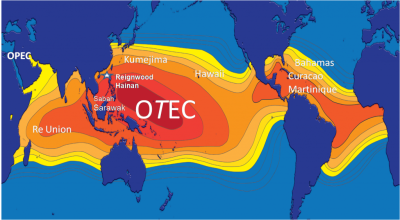
Energy from the sun heats the surface water of the ocean. In tropical regions, surface water can be much warmer than deep water. This temperature difference can be used to produce electricity. The Ocean Thermal Energy Conversion (OTEC) system uses a temperature difference (of at least 25o C) to power a turbine to produce electricity. OTEC systems are mostly suited to tropical zones.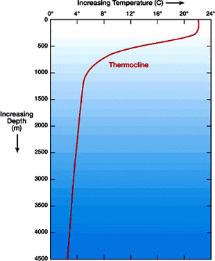
There are three kinds of OTEC systems: closed-cycle, open-cycle, and hybrid.
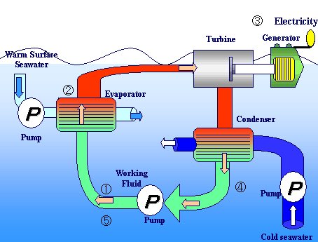
Closed-Cycle Closed-cycle systems
use fluids with a low boiling point, such as ammonia, to rotate a turbine to generate electricity. Warm surface seawater is pumped through a heat exchanger, where the low-boiling-point fluid is vaporized. The expanding vapor turns the turbo-generator. Cold deep seawater—> which is pumped through a second heat exchanger—> then condenses the vapor back into a liquid that is then recycled through the system.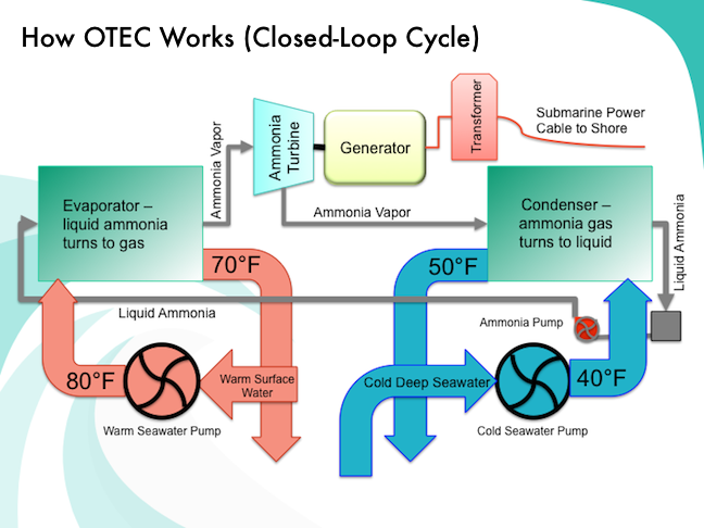
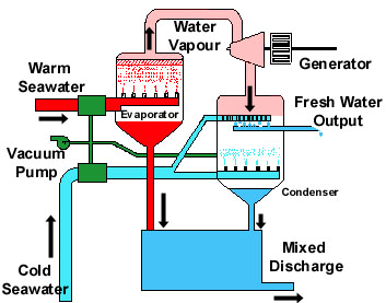
Open-Cycle Open-cycle systems
use the tropical oceans' warm surface water to make electricity. When warm seawater is placed in a low-pressure container, it boils. The expanding steam drives a low-pressure turbine attached to an electrical generator. The steam, which has left its salt behind in the low-pressure container, is almost pure, fresh water. It is condensed back into a liquid by exposure to cold temperatures from deep-ocean water.
A vertical-spout evaporator to convert warm seawater into low-pressure steam for open-cycle plants. Energy conversion efficiencies as high as 97% were achieved.
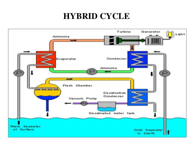
Hybrid systems
Hybrid systems combine the features of closed- and open-cycle systems. In a hybrid system, warm seawater enters a vacuum chamber, where it is flash-evaporated into steam, similar to the open-cycle evaporation process. The steam vaporizes a low-boiling-point fluid (in a closed-cycle loop) that drives a turbine to produce electricity.
OTEC byproducts have potential benefits beyond power production. For example, spent cold seawater from an OTEC plant can chill fresh water in a heat exchanger or flow directly into a cooling system. Simple systems of this type have air-conditioned buildings. OTEC technology also supports chilled-soil agriculture. When cold seawater flows through underground pipes, it chills the surrounding soil. The temperature difference between plant roots in the cool soil and plant leaves in the warm air allows many plants that evolved in temperate climates to be grown in the subtropics. Cold-water delicacies, such as salmon and lobster, thrive in the nutrient-rich, deep seawater culled from the OTEC process. Microalgae such as Spirulina, a health food supplement, also can be cultivated in the deep-ocean water. Finally, an advantage of open or hybrid-cycle OTEC plants is the production of fresh water from seawater. Theoretically, an OTEC plant that generates 2 megawatts of net electricity could produce about 4,300 cubic meters of desalinated water each day.
Environmental and Economic Challenges
In general, careful site selection is key to keeping the environmental effects of OTEC minimal. OTEC experts believe that appropriate spacing of plants throughout tropical oceans can nearly eliminate any potential negative effects on ocean temperatures and marine life. OTEC power plants require substantial capital investment upfront. OTEC researchers believe private sector firms probably will be unwilling to make the enormous initial investment required to build large-scale plants until the price of fossil fuels increases dramatically or national governments provide financial incentives. Another factor hindering the commercialization of OTEC is that there are only a few hundred land-based sites in the tropics where deep-ocean water is close enough to shore to make OTEC plants feasible.
Australian OTEC Initiatives - Townsville Queensland
overview of heat engines- OTEC is a very large heat engine
- all engines need is a cold end and hot end, and take energy out of system
- 8 km pipe costs many millions of dollars and was only 30cm diameter
- Solomon islands - only want 50MW, prove system at smaller scaleclassic engines, rankine cycle (type of system needed for OTEC, as well as organic rankine cycle engine at use in the artesian basin - Birdsville)
- use ammonia as working fluid - at right pressure, liquid phase or vapour
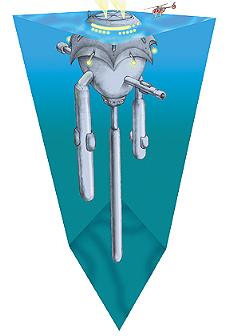
proposed OTEC device for use offshore of the Great Barrier Reef
Rankine cycle
- require 20 degrees celsius difference between hot and cold end
- OTEC requires pipe down to depths - 500 to 700 m deep
- the ocean is on average 4 km deep and cold about 4 degrees
- there is a tiny bit of the ocean, the surface waters in the tropics where the water is warm
- Queensland coast - temperature outside shelf always over 24 degrees, and has cold water in depths after 700m, rate of temp drops less steeply, 750m a good number temp drops similar in all oceans
- Townsville, at latitude 19, is at southern end of ocean temp range required for OTEC karnot efficiency - limits efficiency of heat engines (differential between hot and cold end)
- OTEC efficiency around 3-4%
- other problems is power cable to mainland, moorings and permits, salt water environment floating OTEC, or OTEC on continental shelf (or on land) consideration of the figures for a 1,000MW plant assume 3% efficiency, require 1,000 cubic meters/sec flow rate, pipe of radius of 10m with flow of 3m/s - approximately the same flow of Tully river in moderate flood
- energy loss is relatively small as pumping head is equivalent about 6m in air - perhaps 60MW
- waste water plume - high nutrients, plume must be discharged below thermocline to prevent mixing of nutrient rich waters with warm surface waters
Risk assessment
- thousands of litres of ammonia, size of structure would be much
greater than what is currently on reef (pontoons), more like the size
of an oil rig consideration of environmental risks
1. installation esp. pipes and moorings
2. operation eg. water discharges
3. accidents ( eg spill of ammonia) ammonia should evaporate quickly from the sea surface if spilt structure not necessarily the killer, but nutrients on the reef (community interest) - effect of nutrient on fishing (esp game fishing- black marlin, off Cairns) building into development discharge at equivalent ocean temp
- what lives in the ocean 750 metres below sea level? Giant squid? Billfish?
- life of structure, and maintenance costs 20-30 year life - same as a ship cf. power station life of 50 years
- What about using waste discharge from power plants and industry to create the heat differential for power production - less flow, but already flow rate, or temp differential between rivers and ocean
- heat water using the sun and use cold water
- what about using cold water to cool surface water - as a potential solution to coral bleaching
- Unlike most renewables, OTEC runs 24h a day and thus could be used as base load power
- 120ML of freshwater a day
- what about using the system to use with cooling water of coal power stations, like at mt isa use this as proof of system - eg 10MW
- Cooktown needs 40 MW and has its own grid need energy demand, Cooktown and Cairns would not use up 100MW possibility of putting an OTEC plant on shore and running the pipe to the shelf consideration of the size of the water pipes? 10 metres diameter the recent water pipe laying process between Pallaranda and Magnetic Island
- 8 km pipe costs many millions of dollars and was only 30cm diameter Solomon islands - only want 50MW, prove system at smaller scale
Tidal Power
Tidal power systems are best suited to high latitude sub-polar locations where particularly long narrowing bays where very large tidal ranges may be expected. There are currently three different ways to get tidal energy:- tidal streams,
- tidal barrages,
- and tidal lagoons
Tidal Streams
Placing turbines in tidal streams is complex, because the machines are large and disrupt the tide they are trying to harness. The environmental impact could be severe, depending on the size of the turbine and the site of the tidal stream. Turbines are most effective in shallow water. This produces more energy and allows ships to navigate around the turbines. A tidal generator's turbine blades also turn slowly, which helps marine life avoid getting caught in the system.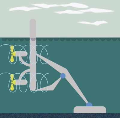
Tidal Barrage
Another type of tidal energy generator uses a large dam called a barrage. With a barrage, water can spill over the top or through turbines in the dam because the dam is low. Barrages can be constructed across tidal rivers, bays, and estuaries.
Turbines inside the barrage harness the power of tides the same way a river dam harnesses the power of a river. The barrage gates are open as the tide rises. At high tide, the barrage gates close, creating a pool, or tidal lagoon. The water is then released through the barrage's turbines, creating energy at a rate that can be controlled by engineers.
The environmental impact of a barrage system can be quite significant. The land in the tidal range is completely disrupted. The change in water level in the tidal lagoon might harm plant and animal life. The salinity inside the tidal lagoon lowers, which changes the organisms that are able to live there. As with dams across rivers, fish are blocked into or out of the tidal lagoon. Turbines move quickly in barrages, and marine animals can be caught in the blades. With their food source limited, birds might find different places to migrate.
A barrage is a much more expensive tidal energy generator than a single turbine. Although there are no fuel costs, barrages involve more construction and more machines. Unlike single turbines, barrages also require constant supervision to adjust power output.
Plant can use two sources of energy: tidal energy and river current energy . The barrage has led to an increased level of silt in the habitat. Native aquatic plants suffocate in silt, and a flatfish called plaice is now extinct in the area. Other organisms, such as cuttlefish, a relative of squids, now thrive in the Rance estuary. Cuttlefish prefer cloudy, silty ecosystems.
Tidal Lagoon
The final type of tidal energy generator involves the construction of tidal lagoons. A tidal lagoon is a body of ocean water that is partly enclosed by a natural or manmade barrier. Tidal lagoons might also be estuaries and have freshwater emptying into them.
A tidal energy generator using tidal lagoons would function much like a barrage. Unlike barrages, however, tidal lagoons can be constructed along the natural coastline. A tidal lagoon power plant could also generate continuous power. The turbines work as the lagoon is filling and emptying. The environmental impact of tidal lagoons is minimal. The lagoons can be constructed with natural materials like rock. They would appear as a low breakwater (sea wall) at low tide, and be submerged at high tide. Animals could swim around the structure, and smaller organisms could swim inside it. Large predators like sharks would not be able to penetrate the lagoon, so smaller fish would probably thrive. Birds would likely flock to the area.
But the energy output from generators using tidal lagoons is likely to be low. There are no functioning examples yet.
Wave Power
As an ocean wave passes a stationary position the surface of the sea changes in height, water near the surface moves as it losses its kinetic and potential energy, which affects the pressure under the surface. The periodic or oscillatory nature of ocean waves means that we can use a variety of different Wave Energy Devices to harness the energy produced by the oceans waves.The problem lies in that the oscillatory frequency of an ocean wave is relatively slow and is much less than the hundreds of revolutions per minute required for electric power generation. Then a great variety of wave energy devices and designs are available to convert these slow-acting, reversing wave forces into the high speed, unidirectional rotation of a generator shaft.
There are three fundamental but very different wave energy devices used in converting wave power into electric power, and these are:
- 1. Wave Profile Devices These are wave energy devices which turn the oscillating height of the oceans surface into mechanical energy.
- 2. Oscillating Water Columns These are wave energy devices which convert the energy of the waves into air pressure.
- 3. Wave Capture Devices These are wave energy devices which convert the energy of the waves into potential energy.
Wave Profile Devices
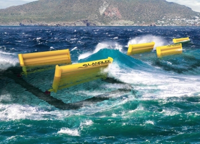
Wave profile devices are a class of wave energy device which floats on or near to the sea surface and moves in response to the shape of the incident wave or, for submersible devices, it moves up and down under the influence of the variations in underwater pressure as a wave moves by.Most types of wave profile devices float on the surface absorbing the wave energy in all directions by following the movements of waves at or near the sea surface, just like a float. The only wave energy devices that use wave profiling have been in practical use for some time, although on a fairly small-scale, are those used for powering navigation buoys.
If the physical size of the wave profile device is very small compared to the periodic length of the wave, this type of wave energy device is called a “point absorber”. If the size of the device is larger or longer than the typical periodic wavelength, it is called a linear absorber, but more commonly they are collectively known as wave attenuators.
The main difference between the two wave energy devices is how the oscillating system converts the wave energy between the absorber and a reaction point. This energy absorption can be achieved either by a floating body, an oscillating solid member or oscillating water within a buoys structure itself.
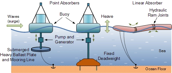
The waves energy is absorbed using vertical motion (heave), horizontal motion in the direction of wave travel (surge), angular motion about a central axis parallel to the wave crests (pitch) or angular motion about a vertical axis (yaw) or a combination of all four with the energy being generated by reacting these different movements against some kind of fixed resistance called a reaction point.
To make efficient use of the force generated by the wave, we need some kind of force reaction. In other words, we want the waves force on the float to react against another rigid or semi-rigid body. Reaction points can be inertial masses such as heavy suspended ballast plates, sea-floor anchors or a fixed dead-weight or pile as shown.
The pitching and heaving of the waves causes a relative motion between an absorber and reaction point. The wave energy device above, uses a heavy ballast plate suspended below the floating buoy. The buoy is prevented from floating away by a mooring line attached to a sea-floor anchor. This mooring line allows the point absorber to operate offshore in deeper waters.
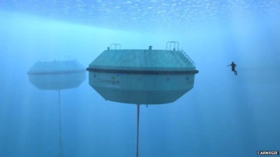
As the buoy bobs up-and-down in the waves, a oscillatory mutual force reaction is generated between the freely moving absorber and the heavy plate causing a hydraulic pump in between to rotate a generator producing electricity. The middle wave energy device operates in a similar manner to the previous floating buoy device. The difference this time is that the freely heaving buoy reacts against a fixed reaction point such as a fixed dead-weight on the ocean floor. As this type of point absorber is bottom mounted, it is operated in shallower near shore locations.
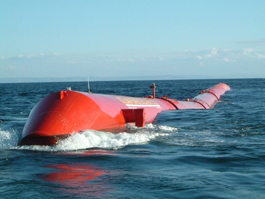
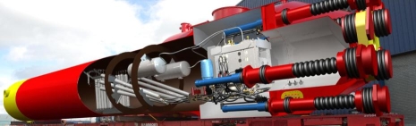
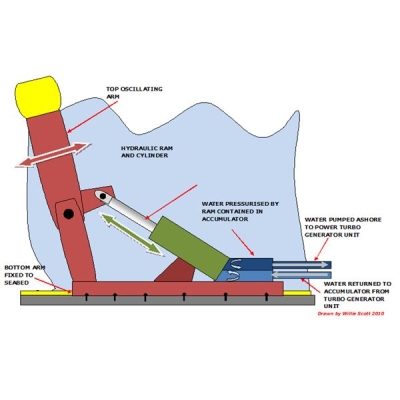
The third device is an example of a linear absorber (wave attenuator) which floats on the surface of the water. It to is tethered to the ocean floor so that it can swing perpendicularly towards the incoming waves. As the waves pass along the length of this snake like wave energy device, they cause the long cylindrical body to sag downwards into the troughs of the waves and arch upwards when the waves crest is passing. Connecting joints along the body of the device flex in the waves exerting a great deal of force which is used to power a hydraulic ram at each joint. The hydraulic ram drives oil through a hydraulic motor which drives a generator, producing the electricity.
Oscillating Water Column
The Oscillating Water Column, (OWC) is a popular shoreline wave energy device normally positioned onto or near to rocks or cliffs which are next to a deep sea bottom. They consist of a partly submerged hollow chamber fixed directly at the shoreline which converts wave energy into air pressure.The structure used to capture the waves energy could be a natural cave with a blow hole or a man made chamber or duct with a wind turbine generator located at the top well above the waters surface. Either way, the structure is built perpendicular to the waves with part of the ocean surface trapped inside the chamber which itself is open to the sea below the water line. The constant ebbing and flowing motion of the waves forces the trapped water inside the chamber to oscillate in the vertical up-down direction.
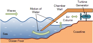
As the incident waves outside enter and exit the chamber, changes in wave movement on the opening cause the water level within the enclosure to oscillate up and down acting like a giant piston on the air above the surface of the water, pushing it back and forth. This air is compressed and decompressed by this movement every cycle. The air is channelled through a wind turbine generator to produce electricity as shown.
The type of wind turbine generator used in an oscillating water column design is the key element to its conversion efficiency. The air inside the chamber is constantly reversing direction with every up-and-down movement of the sea water producing a sucking and blowing effect through the turbine. If a conventional turbine was used to drive the attached generator, this too would be constantly changing direction in unison with the air flow. To overcome this problem the type of wind turbine used in oscillating water column schemes is called a Wells Turbine.
a Wells turbine
The Wells turbine has the remarkable property of rotating in the same direction regardless of the direction of air flow in the column. The kinetic energy is extracted from the reversing air flow by the Wells turbine and is used to drive an electrical induction generator. The speed of the air flow through the wells turbine can be enhanced by making the cross-sectional area of the wave turbines duct much less than that of the sea column.
As with other wave energy converters, oscillating wave column technology produces no greenhouse gas emissions making it a non-polluting and renewable source of energy, created by natural transfer of wind energy through a wells turbine. The advantage of this shoreline scheme is that the main moving part, the turbine can be easily removed for repair or maintenance because it is on land. The disadvantage though is that, as with the previous wave energy devices, the oscillating wave columns output is dependent on the level of wave energy, which varies day by day according to the season.
Wave Capture Device
A wave capture device, or more commonly an overtopping device, elevates ocean waves to a holding reservoir above sea level. Wave energy is converted into potential energy by lifting the water up onto a higher level.There are two basic wave capture designs
- overtopping device / impoundment device
- funnelling device
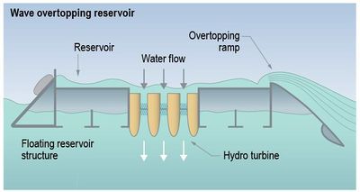
Wave Capture - Overtopping Device
The wave overtopping device uses a ramp design on the device to elevate part of the incoming waves above their natural height. The basic impoundment structure can be either fixed or a floating structure tethered to the sea bed As the waves hit the structure they flow up a ramp and over the top (hence the name overtopping, into a raised water impoundment reservoir on the device in order to fill it. Once captured, the potential energy of the trapped water in the reservoir is extracted using gravity as the water returns to the sea.
Wave Capture - Funnelling Device
The channel is funnel shaped which is wide towards the sea where the waves enter and gradually narrows towards an impoundment reservoir at the other end. As the waves propagate along the narrowing channel, the wave height is lifted due to the funnelling effect to a level exceeding the horizontal upper edge of the channel wall, excess water from the wave is allowed to spill into a confined basin above the normal sea level. As the water is now at a height above the sea level, the potential energy of the water trapped in the basin is then extracted by draining the water back to the sea through.
Other such wave capture devices are located at the shoreline were the waves are channelled along a horizontal man made channel. This
We now know how wave energy works and one of the main advantages of wave energy devices is that besides the generating turbine there are no moving parts. Unfortunately, shoreline overtopping schemes have a relatively low power output due to their low head and are only suitable for sites where there is a deep water shoreline and a low tidal range of less than about a metre. To overcome some of these limitations, floating offshore capture devices have been developed, but they too require sufficient wave power to fill the impoundment reservoir.